

Hardware components | ||||||
 |
| × | 1 | |||
| × | 1 | ||||
Software apps and online services | ||||||
| ||||||
 |
| |||||
This is NOT an automatic white balance (AWB) algorithm. True AWB algorithms do not need markers in order to do their magic, and are therefore much more complex in their implementations.
For the purpose of this project, and to avoid confusion with true AWB, I will be calling this implementation "Automatic Activation of a Simple White Balance", or AASWB.
IntroductionYou may have noticed in my previous project, Quad Face Detection with the UltraZed-EV and Multi-Cam FMC, that the white balance of the video content was not quite right.
This is simply because there is not any white balance algorithm running in the design. It is possible to adjust the white balance manually, but this is a tedious process.
This project takes a look at using marker-based augmented reality to activate a simple white balance algorithm.
Let's get started !
Automatic ActivationIn order to automatically activate the simple white balance algorithm, I will reuse the marker based chart detection that was implemented in the following project:
In this project, we created a gstreamer plug-in that was used with the v4l2src and kmssink plugins, to create the following pipeline.
We will use charts 2 and 3 that were created in that project.
Chart 2 is used for the following tasks:
- identify the "white reference" region of interest
- calculate the color averages for the BGR components in the white region
- call a script that will perform the actual white balance algorithm
Chart 3 (Histogram) is used for visualization purposes, displaying the color histograms in the "white region".
Notice that we are using a new feature implemented in the markerdetect plugin, which will call a script with the three color averages as arguments.
This is accomplished by specifying values for the following two properties:
- wb-script : location of script to call for white balance (default = NULL)
- wb-skip-frames : number of frames to skip between calls to wb-script (default = 0)
For the quad camera FMC, we will define pipelines for each of the four cameras. The first camera will implement the marker detect (with white balance script), and the other three cameras will implement face detection.
For simplicity, and in order to allow users to easily experiment further, the simple white balance algorithm has been implemented in a script.
Using the previously described technique, we have located a region where we know the content to be gray (some shade of white), and calculate the average values for each of the blue, green, and red components.
This allows us to use the very simple "Grey World Model", in which it is expected for the blue, green, and red pixels to have the same intensity.
The algorithm, therefore, consists of adjusting the gains for the blue, green, and red components in the image sensors.
For the Quad AR0231AT Camera FMC Bundle, these gains are made available via the V4L2 API. If we query the AR0231 image sensor for camera 0, we get the following information:
root@uz7ev-evcc-quadcam-2020-2:~# yavta --no-query -l /dev/v4l-subdev0
Device /dev/v4l-subdev0 opened.
--- User Controls (class 0x00980001) ---
control 0x0098090e `AR0231 Red Balance' min 0 max 2047 step 1 default 128 current 173.
control 0x0098090f `AR0231 Blue Balance' min 0 max 2047 step 1 default 619 current 394.
control 0x00980911 `AR0231 Exposure' min 16 max 1339 step 1 default 16 current 1000.
control 0x00980913 `AR0231 Digital Gain' min 0 max 2047 step 1 default 512 current 606.
control 0x00980914 `AR0231 Horizontal Flip' min 0 max 1 step 1 default 0 current 0.
control 0x00980915 `AR0231 Vertical Flip' min 0 max 1 step 1 default 0 current 0.
control 0x00980924 `AR0231 Green Balance' min 0 max 2047 step 1 default 145 current 157.
--- Image Source Controls (class 0x009e0001) ---
control 0x009e0903 `AR0231 Analog Gain' min 0 max 14 step 1 default 7 current 5.
--- Image Processing Controls (class 0x009f0001) ---
control 0x009f0903 `AR0231 Test Pattern' min 0 max 5 step 1 default 0 current 0.
  0: Disabled (*)
  1: Solid Red
  2: Solid Green
  3: Solid Blue
  4: Color Bars (full)
  5: Color Bars (f2grey)
9 controls found.
root@uz7ev-evcc-quadcam-2020-2:~#
The V4L controls that interest us are the following:
- 0x0098090e : AR0231 Red Balance (range 0-2047)
- 0x0098090f : AR0231 Blue Balance (range 0-2047)
- 0x00980924 : AR0231 Green Balance (range 0-2047)
The simple white balance algorithm is implemented in a script (quadcam_aaswb.sh):
...
DEFAULT_PATH="/dev/v4l-subdev"

AR0231_COLOR_GAIN_RED="0x0098090e"
AR0231_COLOR_GAIN_BLUE="0x0098090f"
AR0231_COLOR_GAIN_GREEN="0x00980924"
...
# Get current values
val=0
subnode="$DEFAULT_PATH$val"
b_gain_str=$(yavta --no-query -r "$AR0231_COLOR_GAIN_BLUE" "$subnode" 2>&1)
g_gain_str=$(yavta --no-query -r "$AR0231_COLOR_GAIN_GREEN" "$subnode" 2>&1)
r_gain_str=$(yavta --no-query -r "$AR0231_COLOR_GAIN_RED" "$subnode" 2>&1)
b_gain=$(echo $b_gain_str | cut -d' ' -f 7)
g_gain=$(echo $g_gain_str | cut -d' ' -f 7)
r_gain=$(echo $r_gain_str | cut -d' ' -f 7)
...
# Define targeted color average
x_mean=150
...
# Adjust gains according to color averages
b_delta=$(( x_mean - b_mean ))
g_delta=$(( x_mean - g_mean ))
r_delta=$(( x_mean - r_mean ))
# large values cause oscillations, need to dampen adjustments
b_delta=$(( b_delta > +50 ? +50 : b_delta ))
b_delta=$(( b_delta < -50 ? -50 : b_delta ))
g_delta=$(( g_delta > +50 ? +50 : g_delta ))
g_delta=$(( g_delta < -50 ? -50 : g_delta ))
r_delta=$(( r_delta > +50 ? +50 : r_delta ))
r_delta=$(( r_delta < -50 ? -50 : r_delta ))
b_adjust=$(( b_delta/4 ))
g_adjust=$(( g_delta/4 ))
r_adjust=$(( r_delta/4 ))
# apply adjustments to color gains
BLUE_GAIN_VALUE=$((  b_gain + b_adjust ))
GREEN_GAIN_VALUE=$(( g_gain + g_adjust ))
RED_GAIN_VALUE=$((   r_gain + r_adjust ))
...
echo "QuadCam AASWB : BGR Averages = $b_mean/$g_mean/$r_mean | BGR Gains = $BLUE_GAIN_VALUE/$GREEN_GAIN_VALUE/$RED_GAIN_VALUE ($b_adjust/$g_adjust/$r_adjust)"

for val in {0..3}
do
  subnode="$DEFAULT_PATH$val"
  yavta --no-query -l "$subnode" > /dev/null 2>&1
  yavta --no-query -w "$AR0231_COLOR_GAIN_RED $RED_GAIN_VALUE" "$subnode"
  yavta --no-query -w "$AR0231_COLOR_GAIN_BLUE $BLUE_GAIN_VALUE" "$subnode"
  yavta --no-query -w "$AR0231_COLOR_GAIN_GREEN $GREEN_GAIN_VALUE" "$subnode"
done
In summary, the script is performing the following simple calculations:
- subtract the actual average value (*_mean) from our targeted value (x_mean)
- clip the difference (*_delta) to prevent oscillations in the feedback loop
- dampen the difference (*_delta) to further prevent oscillations
In order to facilitate launching the example, create the following launch script (launch_quadcam_aaswb.sh) on your embedded platform (the capture pipeline configuration has been omitted for clarify):
gst-launch-1.0  \
    v4l2src device=/dev/video2 io-mode=4 ! \
    video/x-raw, width=640, height=360, format=BGR, framerate=30/1 ! \
    markerdetect wb-script="~/quadcam_aaswb.sh" wb-skip-frames=0 ! \
    fpsdisplaysink video-sink="kmssink bus-id=b0050000.v_mix plane-id=38 \
    render-rectangle=\"<0,0,640,360>\"" sync=false fullscreen-overlay=true \
    \
    v4l2src device=/dev/video3 io-mode=4 ! \
    video/x-raw, width=640, height=360, format=BGR, framerate=30/1 ! \
    queue ! vaifacedetect ! queue ! \
    fpsdisplaysink video-sink="kmssink bus-id=b0050000.v_mix plane-id=39 \
    render-rectangle=\"<640,0,640,360>\"" sync=false fullscreen-overlay=true \
    \
    v4l2src device=/dev/video4 io-mode=4 ! \
    video/x-raw, width=640, height=360, format=BGR, framerate=30/1 ! \
    queue ! vaifacedetect ! queue ! \
    fpsdisplaysink video-sink="kmssink bus-id=b0050000.v_mix plane-id=40 \
    render-rectangle=\"<0,360,640,360>\"" sync=false fullscreen-overlay=true \
    \
    v4l2src device=/dev/video5 io-mode=4 ! \
    video/x-raw, width=640, height=360, format=BGR, framerate=30/1 ! \
    queue ! vaifacedetect ! queue ! \
    fpsdisplaysink video-sink="kmssink bus-id=b0050000.v_mix plane-id=41 \
    render-rectangle=\"<640,360,640,360>\"" sync=false fullscreen-overlay=true \
Notice the one line that instantiates the marker detect gstreamer plug-in, with the wb-script and wb-skip-frames properties:
markerdetect wb-script="~/quadcam_aaswb.sh" wb-skip-frames=0 ! \The complete scripts have been provided as attachments in the Code section at the end of this project. They need to be copied to the root directory (/home/root, or ~/).
Known LimitationsThe implementation described in this project has several limitations.
Although the white balance algorithm is being calculated on camera 0, the resulting gains are being applied to all four cameras. This can be changed if needed.
Another important point to highlight is that the exposure is expected to be within a reasonable range. If camera 0 cannot detect the markers on the charts, then the algorithm will obviously not work.
For the experiment that I did in my office space, this was set as follows:
...
DEFAULT_PATH="/dev/v4l-subdev"
...
AR0231_EXPOSURE="0x00980911"
AR0231_DIGITAL_GAIN="0x00980913"
AR0231_ANALOG_GAIN="0x009e0903"
...
EXPOSURE_VALUE="1000"
DIGITAL_GAIN_VALUE="606"
ANALOG_GAIN_VALUE="5"
...
for val in {0..3}
do
  subnode="$DEFAULT_PATH$val"
  yavta --no-query -l "$subnode"
  yavta --no-query -w "$AR0231_EXPOSURE $EXPOSURE_VALUE" "$subnode"
  yavta --no-query -w "$AR0231_DIGITAL_GAIN $DIGITAL_GAIN_VALUE" "$subnode"
  yavta --no-query -w "$AR0231_ANALOG_GAIN $ANALOG_GAIN_VALUE" "$subnode"
done
...
The exposure and general digital/analog gains may need to be adjusted, according to your specific lighting conditions, especially under low light conditions, or in bright sunlight.
Finally, in my simple white balance implementation, I am adjusting the BGR gains in order to reach BGR averages of 150. However, if for any reason the intensity of lighting is varying (ie. clouds), this will be a moving target. In this case, it may be more appropriate to define the target as the green (G) average. This can be achieved in the script by defining the x_mean as follows:
# Define targeted color average
#x_mean=150
x_mean=g_meanPre-built Vitis-AI 1.3 SD card images have been provided for the following Avnet platforms:
- uz7ev_evcc_quadcam : UltraZed-EV Starter Kit + Quad Camera FMC
The download links for the pre-built SD card images can be found here:
- Vitis-AI 1.3 Flow for UZ7EV + QuadCam : http://avnet.me/vitis-ai-1.3-quadcam
Once downloaded, and extracted, the.img file can be programmed to a 16GB micro SD card.
0. Extract the archive to obtain the .img file
1. Program the board specific SD card image to a 16GB (or larger) micro SD card
a. On a Windows machine, use Balena Etcher or Win32DiskImager (free opensource software)
b. On a linux machine, use Balena Etcher or use the dd utility
$ sudo dd bs=4M if=Avnet-{platform}-Vitis-AI-1-3-{date}.img of=/dev/sd{X} status=progress conv=fsyncWhere {X} is a smaller case letter that specifies the device of your SD card. You can use “df -h” to determine which device corresponds to your SD card.
Step 2 - Clone the source code repositoryThe source code used in this project can be obtained from the following repositories:
If you have an active internet connection, you can simply clone the repositories to the root directory of your embedded platform:
$ cd ~
$ git clone https://github.com/AlbertaBeef/vitis_ai_gstreamer_pluginsThe gstreamer plug-in can be built on the UltraZed-EV Starter Kit using the make command:
$ cd vitis_ai_gstreamer_plugins
$ cd markerdetect
$ make
Once compiled, the gstreamer plug-in can be installed as follows:
$ cp libgstmarkerdetect.so /usr/lib/gstreamer-1.0/.The installation of the gstreamer plug-in can be verified with the gst-inspect-1.0 utility:
$ gst-inspect-1.0 | grep markerdetect
Factory Details:
  Rank                     none (0)
  Long-name                Marker detection using the OpenCV Library
  Klass                    Video Filter
  Description              Marker Detection
  Author                   FIXME <fixme@example.com>

Plugin Details:
  Name                     markerdetect
  Description              Marker detection using the OpenCV Library
  Filename                 /usr/lib/gstreamer-1.0/libgstmarkerdetect.so
  Version                  0.0.0
  License                  LGPL
  Source module            markerdetect
  Binary package           OpenCV Library
  Origin URL               http://avnet.com

GObject
 +----GInitiallyUnowned
       +----GstObject
             +----GstElement
                   +----GstBaseTransform
                         +----GstVideoFilter
                               +----GstMarkerDetect

Pad Templates:
  SRC template: 'src'
    Availability: Always
    Capabilities:
      video/x-raw
                 format: { (string)BGR }
                  width: [ 1, 1920 ]
                 height: [ 1, 1080 ]
              framerate: [ 0/1, 2147483647/1 ]

  SINK template: 'sink'
    Availability: Always
    Capabilities:
      video/x-raw
                 format: { (string)BGR }
                  width: [ 1, 1920 ]
                 height: [ 1, 1080 ]
              framerate: [ 0/1, 2147483647/1 ]

Element has no clocking capabilities.
Element has no URI handling capabilities.

Pads:e--
  SINK: 'sink'
    Pad Template: 'sink'
  SRC: 'src'
    Pad Template: 'src'

Element Properties:
  name                : The name of the object
                        flags: readable, writable
                        String. Default: "markerdetect0"
  parent              : The parent of the object
                        flags: readable, writable
                        Object of type "GstObject"
  qos                 : Handle Quality-of-Service events
                        flags: readable, writable
                        Boolean. Default: true
  wb-script           : White Balance script.
                        flags: readable, writable
                        String. Default: null
  wb-skip-frames      : White Balance skip frames.
                        flags: readable, writable
Integer. Range: 0 - 2147483647 Default: 0Before launching the example, we want to configure the resolution of our HDMI monitor to 1280x720. This is not required, in which case the output will occupy the top-left portion of the screen.
$ modetest-hdmi -s 46@44:1280x720-60@AR24The example can be launched using the script we just created:
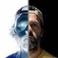
$ ./launch_quadcam_aawsb.shThe following animated GIF (actual speed) illustrates the AAWSB algorithm, for the case of adjusting between a bright LED lighting source, to the ambient lighting of my office.
If we zoom in on the top-left output, we can see the following color histograms before and after white balance.
When white balanced, the blue, green, and red histograms have similar shapes and overlap on each other.
The following animated GIF (2x speed) illustrates the AAWSB algorithm, adjusting to varying lighting conditions, as I turn on and off the bright LED lighting source.
The following is a sample output from the AASWB algorithm script, for the case of adjusting between a bright LED lighting source, to the ambient lighting of my office.
QuadCam AASWB : BGR Averages = 244/224/216 | BGR Gains = 631/173/192 (-12/-12/-12)
QuadCam AASWB : BGR Averages = 244/221/218 | BGR Gains = 619/161/180 (-12/-12/-12)
QuadCam AASWB : BGR Averages = 244/221/220 | BGR Gains = 607/149/168 (-12/-12/-12)
QuadCam AASWB : BGR Averages = 243/209/210 | BGR Gains = 595/137/156 (-12/-12/-12)
QuadCam AASWB : BGR Averages = 242/198/199 | BGR Gains = 583/125/144 (-12/-12/-12)
QuadCam AASWB : BGR Averages = 241/187/189 | BGR Gains = 571/116/135 (-12/-9/-9)
QuadCam AASWB : BGR Averages = 236/174/168 | BGR Gains = 559/110/131 (-12/-6/-4)
QuadCam AASWB : BGR Averages = 238/162/167 | BGR Gains = 547/107/127 (-12/-3/-4)
QuadCam AASWB : BGR Averages = 235/152/158 | BGR Gains = 535/107/125 (-12/0/-2)
QuadCam AASWB : BGR Averages = 227/142/149 | BGR Gains = 523/109/125 (-12/2/0)
QuadCam AASWB : BGR Averages = 227/142/149 | BGR Gains = 511/111/125 (-12/2/0)
QuadCam AASWB : BGR Averages = 218/144/147 | BGR Gains = 499/112/125 (-12/1/0)
QuadCam AASWB : BGR Averages = 218/144/147 | BGR Gains = 487/113/125 (-12/1/0)
QuadCam AASWB : BGR Averages = 213/145/146 | BGR Gains = 475/114/126 (-12/1/1)
QuadCam AASWB : BGR Averages = 207/146/146 | BGR Gains = 463/115/127 (-12/1/1)
QuadCam AASWB : BGR Averages = 202/147/147 | BGR Gains = 451/115/127 (-12/0/0)
QuadCam AASWB : BGR Averages = 198/148/149 | BGR Gains = 439/115/127 (-12/0/0)
QuadCam AASWB : BGR Averages = 193/149/149 | BGR Gains = 429/115/127 (-10/0/0)
QuadCam AASWB : BGR Averages = 189/149/149 | BGR Gains = 420/115/127 (-9/0/0)
QuadCam AASWB : BGR Averages = 184/149/149 | BGR Gains = 412/115/127 (-8/0/0)
QuadCam AASWB : BGR Averages = 180/149/149 | BGR Gains = 405/115/127 (-7/0/0)
QuadCam AASWB : BGR Averages = 176/149/149 | BGR Gains = 399/115/127 (-6/0/0)
QuadCam AASWB : BGR Averages = 174/149/149 | BGR Gains = 393/115/127 (-6/0/0)
QuadCam AASWB : BGR Averages = 171/149/149 | BGR Gains = 388/115/127 (-5/0/0)
QuadCam AASWB : BGR Averages = 168/149/149 | BGR Gains = 384/115/127 (-4/0/0)
QuadCam AASWB : BGR Averages = 166/149/149 | BGR Gains = 380/115/127 (-4/0/0)
QuadCam AASWB : BGR Averages = 164/149/148 | BGR Gains = 377/115/127 (-3/0/0)
QuadCam AASWB : BGR Averages = 163/149/149 | BGR Gains = 374/115/127 (-3/0/0)
QuadCam AASWB : BGR Averages = 160/149/149 | BGR Gains = 372/115/127 (-2/0/0)
QuadCam AASWB : BGR Averages = 160/149/149 | BGR Gains = 370/115/127 (-2/0/0)
QuadCam AASWB : BGR Averages = 159/149/149 | BGR Gains = 368/115/127 (-2/0/0)
QuadCam AASWB : BGR Averages = 158/149/149 | BGR Gains = 366/115/127 (-2/0/0)
QuadCam AASWB : BGR Averages = 158/149/149 | BGR Gains = 364/115/127 (-2/0/0)
QuadCam AASWB : BGR Averages = 157/149/149 | BGR Gains = 363/115/127 (-1/0/0)
QuadCam AASWB : BGR Averages = 156/149/149 | BGR Gains = 362/115/127 (-1/0/0)
QuadCam AASWB : BGR Averages = 155/149/149 | BGR Gains = 361/115/127 (-1/0/0)
QuadCam AASWB : BGR Averages = 155/149/149 | BGR Gains = 360/115/127 (-1/0/0)
QuadCam AASWB : BGR Averages = 154/149/149 | BGR Gains = 359/115/127 (-1/0/0)
QuadCam AASWB : BGR Averages = 154/149/149 | BGR Gains = 358/115/127 (-1/0/0)
QuadCam AASWB : BGR Averages = 154/149/149 | BGR Gains = 357/115/127 (-1/0/0)
QuadCam AASWB : BGR Averages = 153/149/149 | BGR Gains = 357/115/127 (0/0/0)
QuadCam AASWB : BGR Averages = 153/149/149 | BGR Gains = 357/115/127 (0/0/0)
QuadCam AASWB : BGR Averages = 153/149/149 | BGR Gains = 357/115/127 (0/0/0)
QuadCam AASWB : BGR Averages = 153/149/149 | BGR Gains = 357/115/127 (0/0/0)
QuadCam AASWB : BGR Averages = 153/149/149 | BGR Gains = 357/115/127 (0/0/0)
QuadCam AASWB : BGR Averages = 153/149/149 | BGR Gains = 357/115/127 (0/0/0)
QuadCam AASWB : BGR Averages = 153/149/149 | BGR Gains = 357/115/127 (0/0/0)
QuadCam AASWB : BGR Averages = 153/149/149 | BGR Gains = 357/115/127 (0/0/0)
We can see that the BGR gains are adjusted until the BGR averages approach 150/150/150.
This information can be used to set a static BGR gain configuration. The AAWB script can be executed once to determine the optimal values. Then, a static script can be created for the specific lighting conditions. As an example, the following script will configure the quadcam for my office lighting, using the previous results.
DEFAULT_PATH="/dev/v4l-subdev"

AR0231_COLOR_GAIN_RED="0x0098090e"
AR0231_COLOR_GAIN_BLUE="0x0098090f"
AR0231_COLOR_GAIN_GREEN="0x00980924"

# static color gains for my office lighting
BLUE_GAIN_VALUE=357
GREEN_GAIN_VALUE=115
RED_GAIN_VALUE=127

echo "QuadCam BGR Gains = $BLUE_GAIN_VALUE/$GREEN_GAIN_VALUE/$RED_GAIN_VALUE"

for val in {0..3}
do
  subnode="$DEFAULT_PATH$val"
  yavta --no-query -l "$subnode" > /dev/null 2>&1
  yavta --no-query -w "$AR0231_COLOR_GAIN_RED $RED_GAIN_VALUE" "$subnode"
  yavta --no-query -w "$AR0231_COLOR_GAIN_BLUE $BLUE_GAIN_VALUE" "$subnode"
  yavta --no-query -w "$AR0231_COLOR_GAIN_GREEN $GREEN_GAIN_VALUE" "$subnode"
doneI hope this tutorial will inspire you to experiment wtih augmented reality (AR) on your UltraZed-EV Starter Kit.
Let me know what you think about the simple white balance algorithm. Would you have implemented this differently ?
If there is any other related content that you would like to see, please share your thoughts in the comments below.
Revision History2021/05/12 - Initial Version
AcknowledgementsThank you again Tom Simpson for your excellent contributions:
- Creating a Vitis-AI GStreamer Plugin for the Ultra96-V2
- Machine learning example for the ZCU104 with FMC Quad-Camera module from Avnet
Thank you Pantone for your innovative and inspiring color matching app:
- Pantone, Color Matching Card, https://www.pantone.com/pantone-color-match-card
Thank you Adrian Rosebrock for your excellent tutorials on marker based AR:
- Adrian Rosebrock, Generating ArUco markers with OpenCV and Python, PyImageSearch, https://www.pyimagesearch.com/2020/12/14/generating-aruco-markers-with-opencv-and-python/ (accessed on 07 May, 2021)
- Adrian Rosebrock, Detecting ArUco markers with OpenCV and Python, PyImageSearch, https://www.pyimagesearch.com/2020/12/21/detecting-aruco-markers-with-opencv-and-python/ (accessed on 07 May, 2021)


Comments