

Hardware components | ||||||
 |
| × | 1 | |||
| × | 1 | ||||
 |
| × | 1 | |||
This guide provides detailed instructions for implementing face detection on two (2) cameras using the Ultra96-V2 and Dual-Camera Mezzanine.
This guide will describe how to download and install the pre-built SD card images, and execute the AI applications on the hardware.
Design OverviewThe following block diagram illustrates the hardware design included in the pre-built image.
The pre-built SD card image includes a hardware design built with Vitis with the following DPU configurations:
- u96v2_sbc_dualcam: 1 x B1152 (low RAM usage), 200MHz/400MHz
The following images capture the resource utilization with and without the DPU, in the form of resource utilization.
The following images capture the resource utilization with and without the DPU, in the form of resource placement.
The following image illustrates the dual capture pipeline for the dual camera mezzanine.
The dual-camera mezzanine makes use of MIPI in order to connect the image cameras to the processing board.
The hardware design implemented in the PL includes the following components:
- MIPI CSI-2 RX receiver IP core
- Image Pipeline : implemented with Color-Space-Conversion, and Scaler
- Frame Buffer Write : the DMA engine implementing writes to external DDR
It is important to known that the AP1302 ISP receives the stereo images and generates a single side-by-side-image, as shown below:
Although the side-by-side image reflects the frontal view of the dual camera mezzanine, it is important to know that it contains:
- image from left (L) camera on right side
- image from right (R) camera on left side
This clarification is essential for any stereo processing that is attempted.
When in doubt, or to convince yourself, place your finger in front of one of the cameras and notice which side of the side-by-side image is blocked.
Step 1 - Create the SD cardA pre-built SD card image has been provided for this design.
You will need to download the following pre-built SD card image:
- u96v2_sbc_dualcam :
https://avnet.me/avnet-u96v2_sbc_dualcam-vitis-ai-1.3-image
(2021-09-03 - MD5SUM = bb9831922982e5224a576e7d635da6f8)
The SD card image contains the hardware design (BOOT.BIN, dpu.xclbin), as well as the petalinux images (boot.scr, image.ub, rootfs.tar.gz). It is provided in image (IMG) format, and contains two partitions:
- BOOT – partition of type FAT (size=400MB)
- ROOTFS – partition of type EXT4
The first BOOT partition was created with a size of 400MB, and contains the following files:
- BOOT.BIN
- boot.scr
- image.ub
- init.sh
- platform_desc.txt
- dpu.xclbin
- arch.json
The second ROOTFS partition contains the rootfs.tar.gz content, and is pre-installed with the Vitis-AI runtime packages, as well as the following directories:
- /home/root/dpu_sw_optimize
- /home/root/Vitis-AI, which includes
- pre-built VART samples
- pre-built Vitis-AI-Library samples
- /home/root/gst-tutorial, which includes
- source code for gstreamer plug-ins
- /home/root/scripts, which includes
- launch scripts for demos
Once downloaded, and extracted, the.img file can be programmed to a 16GB micro SD card.
0. Extract the archive to obtain the.img file
1. Program the board specific SD card image to a 16GB (or larger) micro SD card using Balena Etcher (available for Windows and Linux)
Step 2 - Execute the Dual Camera passthroughThis section covers how to execute the default dual camera passthrough example.
2. Boot the target board with the micro SD card that was create in the previous section
System Initialization
3. After boot, launch the dpu_sw_optimize.sh script
$ cd ~/dpu_sw_optimize/zynqmp
$ source ./zynqmp_dpu_optimize.sh
This script will perform the following steps:
- Auto resize SD card’s second (EXT4) partition
- Optimize the DDR memory's QoS configuration for DisplayPort output
4. [Optional] Disable the dmesg verbose output:
$ dmesg -DThis can be re-enabled with the following:
$ dmesg -E5. Validate the Vitis-AI runtime with the dexplorer utility.
For the u96v2_sbc_dualcam target, this should correspond to the following output:
$ dexplorer –whoami
[DPU IP Spec]
IP Timestamp            : 2020-11-02 15:15:00
DPU Core Count          : 1

[DPU Core Configuration List]
DPU Core                : #0
DPU Enabled             : Yes
DPU Arch                : B1152
DPU Target Version      : v1.4.1
DPU Freqency            : 300 MHz
Ram Usage               : Low
DepthwiseConv           : Enabled
DepthwiseConv+Relu6     : Enabled
Conv+Leakyrelu          : Enabled
Conv+Relu6              : Enabled
Channel Augmentation    : Enabled
Average Pool            : Enabled
6. Close the x-windows desktop
$ /etc/init.d/xserver-nodm stopX-windows can be restarted with the following command or simply rebooting the board:
$ /etc/init.d/xserver-nodm restartRunning the dual camera passthrough
7. Change the resolution of the DP monitor to 1920x1080
$ modetest -D fd4a0000.zynqmp-display -s 43@41:1920x1080@AR24 -P 39@41:1920x1080@YUYV -w 40:alpha:0 &This will put the monitor in 1920x1080 resolution, and display the following test pattern.
8. Launch the Dual Camera passthrough script
$ run_1920_1080This will display a side-by-side image of the two AR0144 cameras. Notice that the width is compressed by a factor of 2, which is only to make the image fit on the monitor.
Understanding the dual camera passthrough (optional)
If we look at the "run_1920_1080" script, it is performing the following:
- initialize capture pipeline for dual camera mezzanine
- launch gstreamer pipeline
The gst-launch-1.0 utility is used to launch the following gstreamer pipeline.
gst-launch-1.0 v4l2src device=/dev/video0 io-mode="dmabuf" \
 ! "video/x-raw, width=$OUTPUT_W, height=$OUTPUT_H, format=YUY2, framerate=60/1" \
 ! videoconvert \
 ! kmssink plane-id=39 bus-id=fd4a0000.zynqmp-display render-rectangle="<0,0,$OUTPUT_W,$OUTPUT_H> fullscreen-overlay=true sync=false" \
   -v
The video source for the pipeline is specified with the following lines:
v4l2src device=/dev/video0 io-mode="dmabuf" \
 ! "video/x-raw, width=$OUTPUT_W, height=$OUTPUT_H, format=YUY2, framerate=60/1" \
The video sink for the pipeline is sent to the DisplayPort output with the following lines:
! videoconvert \
 ! kmssink plane-id=39 bus-id=fd4a0000.zynqmp-display render-rectangle="<0,0,$OUTPUT_W,$OUTPUT_H> fullscreen-overlay=true sync=false" \
Investigating the dual camera passthrough (optional)
The gstreamer pipeline can be further investigated using gstreamer's graph capability. In order to enable the generation of graphs, set the following environment variable:
$ export GST_DEBUG_DUMP_DOT_DIR=/tmp/Run the passthrough script again:
$ run_1920_1080The /tmp directory will now contain 5 graphs in .dot format:
0.00.00.196672240-gst-launch.NULL_READY.dot
0.00.00.199938300-gst-launch.READY_PAUSED.dot
0.00.00.289976680-gst-launch.PAUSED_PLAYING.dot
0.01.33.176974490-gst-launch.PLAYING_PAUSED.dot
0.01.33.447639600-gst-launch.PAUSED_READY.dot
Since we are using gst-launch-1.0, a new pipeline graph will be generated on each pipeline state change. This is helpful for debugging our pipeline during caps negotiation. The graph that we are interested in is the fifth graph called "PAUSED_READY".
This .dot file can be converted to pdf, or jpg on a linux machine (with the graphviz package installed) as follows:
dot -Tpdf 0.01.33.447639600-gst-launch.PAUSED_READY.dot > run_1920_1080_graph.pdf
dot -Tjpg 0.01.33.447639600-gst-launch.PAUSED_READY.dot > run_1920_1080_graph.jpg
Here is the resulting jpg pipeline for the previous example:
We can see that the gstreamer pipeline is composed of the following elements:
- GstV4l2Src
- GstCapsFilter
- GstVideoConvert
- GstKMSSink
We can also see that the pipeline has the following configuration:
- 1920x1080 resolution
- YUYV format
The previous "run_1920_1080" application uses the gstreamer infrastructure.
The python examples described in this section make use of the OpenCV API.
If we terminated the X-windows in the previous section, we need to restart it with the following command:
$ /etc/init.d/xserver-nodm restartWe then need to define our display for the X-windows environment as follows:
$ export DISPLAY=:0.0We can then configure the resolution of the dual camera pipeline to 640x480 with BGR color format.
$ cd ~/opencv
$ source ./setup_640_480_bgr.sh
u96v2_sbc_dualcam_ar0144_passthrough.py
In order to launch the python script that performs a simple passthrough, use the following command:
$ python3 u96v2_sbc_dualcam_ar0144_passthrough.pyIn this example the dual side-by-side image is treated as a single image and displayed to the monitor.
while(True):
  # Capture input
  ret, frame = cap.read()

  # Insert your processing here ...
  #frame = cv2.cvtColor(frame, cv2.COLOR_BGR2GRAY)

  # Display output
  cv2.imshow('u96v2_sbc_dualcam_ar0144 - passthrough',frame)
  if cv2.waitKey(1) & 0xFF == ord('q'):
    break
u96v2_sbc_dualcam_ar0144_anaglyph.py
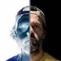
In order to launch the python script that performs a simple stereo processing (anaglyph), use the following command:
$ python3 u96v2_sbc_dualcam_ar0144_anaglyph.pyIn this example, the dual side-by-side image is split into left and right images, for further processing.
while(True):
  # Capture input
  ret, frame = cap.read()

  # Extract left/right images and resize
  right = frame[:,1:w+1,:]
  right = cv2.resize(right,(w2,h))
  left = frame[:,w:w2+1,:]
  left = cv2.resize(left,(w2,h))

  # Calculate anaglyph
  # reference : https://learnopencv.com/making-a-low-cost-stereo-camera-using-opencv/
  # - right : cyan (blue+green)
  anaglyph = right
  # - left : red
  anaglyph[:,:,2] = left[:,:,2]

  # Display output
  cv2.imshow('u96v2_sbc_dualcam_ar0144 - anaglyph',anaglyph)
  if cv2.waitKey(1) & 0xFF == ord('q'):
    break
The anaglyph algorithm is the traditional method for showing 3D videos with the use of colored lenses. The anaglyph implementation is taken from the LearnOpenCV web site:
https://learnopencv.com/making-a-low-cost-stereo-camera-using-opencv/
In order to appreciate the depth of the anaglyph output, a pair of red-cyan glasses are required:
u96v2_sbc_dualcam_ar0144_stereo_face_detection.py
The next example combines face detection with the stereo cameras. In order to launch the python script that performs the stereo face detection, use the following command:
$ python3 u96v2_sbc_dualcam_ar0144_stereo_face_detection.pyIn this example, face detection is performed on each of the left and right images.
# Vitis-AI/DPU based face detector
left_faces = dpu_face_detector.process(left_frame)
right_faces = dpu_face_detector.process(right_frame)
If one face is detected in each image, then the following additional processing is done with the detected faces:
- calculate the centroid (center of bounding box) for each face
- calculate the horizontal distance between both centroids (delta_cx)
- check if the distance (delta_cx) is within a certain range
The output of the example displays both left and right images, each with different annotations.
- image from left (L) camera displayed on the left
- image from right (R) camera displayed on the right
The right image displays annotations which represent the intermediate results, including:
- cyan bounding box + cyan centroid => right face bounding box
- white bounding box + white centroid => left face bounding box
- current value of delta_cx
# if one face detected in each image, calculate the centroids to detect distance range
distance_valid = False
if (len(left_faces) == 1) & (len(right_faces) == 1):

  # loop over the left faces
  for i,(left,top,right,bottom) in enumerate(left_faces):
    left_cx = int((left+right)/2)
    left_cy = int((top+bottom)/2)
    cornerRect(frame2,(left,top,right,bottom),colorR=(255,255,255),colorC=(255,255,255))
    cv2.circle(frame2,(left_cx,left_cy),4,(255,255,255),-1)

  # loop over the right faces
  for i,(left,top,right,bottom) in enumerate(right_faces):
    right_cx = int((left+right)/2)
    right_cy = int((top+bottom)/2)
    cornerRect(frame2,(left,top,right,bottom),colorR=(255,255,0),colorC=(255,255,0))
    cv2.circle(frame2,(right_cx,right_cy),4,(255,255,0),-1)

  delta_cx = abs(left_cx - right)
  delta_cy = abs(right_cy - left_cy)
  message = "delta_cx="+str(delta_cx)
  cv2.putText(frame2,message,(20,20),cv2.FONT_HERSHEY_SIMPLEX,0.75,(255,255,0),2)

  if ( (delta_cx > 15) & (delta_cx < 25) ):
    distance_valid = True
The left image displays annotations for the final result, including:
- left face bounding box in green => if delta_cx is within certain range
- left face bounding box in red => if delta_cx is outside range
# loop over the left faces
for i,(left,top,right,bottom) in enumerate(left_faces):
  if distance_valid == True:
    cornerRect(frame1,(left,top,right,bottom),colorR=(0,255,0),colorC=(0,255,0))
  if distance_valid == False:
    cornerRect(frame1,(left,top,right,bottom),colorR=(0,0,255),colorC=(0,0,255))
Note that if more than one face is detected, there will not be annotations in the right image, and all the detected faces will be displayed in red in the left image.
Feel free to modify the python scripts to experiment with your own ideas.
I hope these python examples provide enough examples to get you started on your own stereo application !
Appendix 1 – Rebuilding the DesignThis section describes how to re-build this design.
The DPU-enabled designs were built with Vitis. With this in mind, the first step is to create a Vitis platform, which can be done with a linux machine, which has the Vitis 2020.2 tools correctly installed.
The following commands will clone the Avnet “bdf”, “hdl”, “petalinux”, and “vitis” repositories, all needed to re-build the Vitis platforms:
git clone https://github.com/Avnet/bdf
git clone –b 2020.2 https://github.com/Avnet/hdl
git clone –b 2020.2 https://github.com/Avnet/petalinux
git clone –b 2020.2 https://github.com/Avnet/vitis
Then, from the “vitis” directory, run make and specify the following target
- u96v2_sbc_dualcam : will re-build the Vitis platform for the Ultra96-V2 Development Board + Dual-Camera Mezzanine
Also specify which build steps you want to perform, in order:
- xsa : will re-build the Vivado project for the hardware design
- plnx : will re-build the petalinux project for the software
- sysroot : will re-build the root file system, used for cross-compilation on the host
- pfm : will re-build the Vitis platform
To rebuild the Vitis platform for the Ultra96-V2 with Dual-Camera, use the following commands:
cd vitis
make u96v2_sbc_dualcam step=xsa
make u96v2_sbc_dualcam step=plnx
make u96v2_sbc_dualcam step=sysroot
make u96v2_sbc_dualcam step=pfm
With the Vitis platform built, you can build the DPU-TRD, as follows:
make u96v2_sbc_dualcam step=dpuFor reference, this build step performs the following:
- clone branch v1.3 of the Vitis-AI repository (if not done so already)
- copy the DPU-TRD to the projects directory, and rename it to {platform}_dpu
- copy the following three files from the vitis/app/dpu directory:- Makefile : modified Makefile- dpu_conf.vh : modified DPU configuration file specifying DPU architecture, etc…- config_file/prj_config : modified configuration file specifying DPU clocks & connectivity
- build design with make
This will create a SD card image in the following directory:
vitis/projects/u96v2_sbc_dualcam_2020_2_dpu/prj/Vitis/binary_container_1/sd_card.imgThis SD card image can be programed to the SD card, as described previously in this tutorial. However, it does not yet contain all the installed runtime packages and pre-compiled applications.
In order to complete the full installation, you will need to follow the instructions in the following sections of the Vitis-AI repository:
- Installing the DNNDK runtime
https://github.com/Xilinx/Vitis-AI/tree/v1.3/demo/DNNDK - Installing the Vitis AI runtime v1.3 (for Edge), and examples
https://github.com/Xilinx/Vitis-AI/tree/v1.3/demo/VART - Installing the Vitis AI Library v1.3 (for Edge), and examples
https://github.com/Xilinx/Vitis-AI/tree/v1.3/demo/Vitis-AI-Library
With the DPU-TRD design built, you can compile the AI-Model-Zoo for this design, as follows:
make u96v2_sbc_dualcam step=zooFor reference, this build step performs the following:
- clone branch v1.3 of the Vitis-AI repository (if not done so already)
- copy the models/AI-Model-Zoo to the projects directory, and rename it to u96v2_sbc_dualcam_2020_2_zoo
- copy the following files from the vitis/app/zoo directory- compile_modelzoo.sh : script to compile all models
In order to perform the actual compilation, perform the steps described below:
==================================================================
Instructions to build AI-Model-Zoo for u96v2_sbc_dualcam_2020_2 platform:
==================================================================
cd projects/u96v2_sbc_dualcam_2020_2_zoo/.
./docker_run.sh xilinx/vitis-ai:1.3.411
source ./compile_modelzoo.sh
==================================================================
Additional Information:
- to compile only one (or a few) models,
remove unwanted model sub-directories from model-list directory
==================================================================
This will create compiled models in the following directory:
vitis/projects/u96v2_sbc_dualcam_2020_2_zoo/vitis_ai_library/modelsThe dual camera mezzanine must be oriented as shown below in order to obtain an image in the correct orientation.
Also, the AR0144 sensors have a lens that can be manually adjusted to obtain a clear focus.
ConclusionI hope this tutorial, with its pre-built SD card image, will help you to get started quickly with Vitis-AI 1.3 on the Ultra96-V2 and Dual-Camera Mezzanine.
If there is any other related content that you would like to see, please share your thoughts in the comments below.
Revision History2021/08/23 - Initial Version
2021/08/25 - Update with stereo face detection script
2021/09/03 - Update build instructions and SD card image
AcknowledgementsI would like to thank Kris Gao and Watson Chow for their initial work on the dual camera design.
I would like to thank Tom Curran, Chris Ammann, and the Witekio team (Florian Rebaudo, Stanislas Bertrand, Thomas Nizan) for their work adding this design to the Avnet git hub repositories.


Comments